Wednesday 14 September 2016

A note on my new blog series: C64 emulator for Android

Note

As remarked in the final post of my series on writing a JavaScript Emulator from scratch, I was planning to do a similar exercise for writing a C64 emulator running on Android.

This blog series, writing a C64 series for Android, has indeed started, and I have already written a couple of posts.

Just for those that couldn't get hold of the link for the new blog-series, here it is:

http://androidemufromscratch.blogspot.co.za/

Enjoy!

Thursday 11 August 2016

Part 21: Implementing Sprites

Foreword

In the previous blog we fixed the garbled screen when we started the game Dan Dare within our emulator Dan Dare within our emulator.

Despite our progress, we ended off the previous blog with Dan Dare and the Treens still invisible.

In this Blog we will bring Dan Dare and the Treens to live. As a matter of fact, Dan Dare and the Treens are sprites, which we haven't implemented yet in our emulator.

So, in this Blog we will implement sprites.

This Blog will conclude my series on Writing a JavaScript emulator scratch.

Introduction to C64 Sprites


A Sprite is a small hi resolution image that you can move around the screen with minimum effort.

On the Commodore 64 the resolution of a Sprite is 24x21 and you can display up to eight sprites simultaneously.

The complexity of Sprites comes in with the fact that they can overlap each other and potentially other graphic objects like text characters. When developing a game involving Sprites, one should specify for the graphics chip which graphic objects are the objects that should be hidden in a case of overlapping.

The VIC II chip uses priorities to allow the developer to specify which objects should be concealed in the case of overlapping. Before we continue, lets us define the term priority within the context of the VIC II chip by means of an example: If Sprite A obscures the view of Sprite B, Sprite A is said to have a higher priority than Sprite B.

The first mechanism for specifying Sprite priority within the VIC-II is via the sprite numbers it self. The lower the sprite number, the higher its priority. For instance, Sprite number 0 will always have the highest priority, therefore it is not possible for another sprite to obscure sprite 0. Likewise, for instance, sprite number two will always obscure sprite number four.

How do specify whether a sprite should appear in front or behind text? You specify this via the sprite collision register at location D01B. Each bit in this register corresponds to a specific sprite. If the bit for a specific sprite is set to a one, this sprite will appear behind text. If the bit is set to a zero, it will appear in front of text.

With all this theory covered, one might wonder: How do you implement sprites within our emulator? This seems like a lot of potential record keeping to determine when to draw a particular sprite in order to ensure that the correct sprite gets concealed.

With HTML5 at our disposal, we should let canvasses do the work for us as much as possible, in order to limit the amount of record keeping we need to do to conceal the correct sprite.

A nice thing about HTML 5 canvases is that you can stack them on top of each other. What is even more attractive about an HTML 5 canvas is that each pixel on it has an alpha channel which you can use to specify transparency.

With above mentioned two properties of a HTML5 canvas, I can already see how canvasses can aid us in dealing with overlapping sprites.

My idea is basically to define the following canvases and stack them on top of each other:

  • Background canvas
  • Canvas for sprites having a priority for appearing behind text
  • Foreground canvas. You will use this canvas to draw text
  • Canvas for sprites having a priority for appearing in front of text
This set of stacked canvases will correctly deal with showing sprites in front or behind text.

To deal with priorities of overlapping sprites, we should be careful about the drawing order of sprites. When we draw sprites, we need to draw them in sequence starting with the lowest priority sprite (e.g. sprite number 7) and working our way up to the highest priority sprite (e.g. sprite number 0).

Let us try to visualise this stacked canvases. I will take the following screen shot from the game Dan Dare as an example:


In this scene, Dan Dare is under water with only a tip of Reed sticking out of the water as seen on the top left of the water.

I will now show you a sequence of screen shots, showing how each individual canvas in our emulator (as in the state by the end of this blog) would look like if you unstack them.

First the background layer:


Next, the canvas for sprites appearing behind text:


Next , the foreground layer:


By far, the most most messy layer is the background layer. This is a side-effect of my attempt to minimise writes to canvasses for performance reasons. Basically I only write to a particular pixel on the background canvas if it is not obscured by the foreground canvas. So, the "dirt" is actually ghost images of a few moments back.

Just one final remark about the messiness about the background canvas. This is quit evident that the game makes extensive use of inverse video. This actually made me click, in the debugging session of my  previous blog, why 81h was used for the screen code of an A instead of one: It is inverse video! With inverse video, bit 7 is always set in the screen code.

Implementing Stacked canvases in HTML 5

Let us implement the stacked canvasses into our index page, as mentioned in the previous section:

...
  <body onkeydown="mykeyboard.onkeydown(event)" onkeyup="mykeyboard.onkeyup(event)">
    <h1>6502 Emulator From Scratch</h1>
    <p>This is JavaScript Test</p>
<div style="position:relative; width:400px; height:284px">
<canvas id="screenBackground" width="400" height="284" style="z-index: 1; position:absolute; left: 0px; top: 0px">

</canvas>

<canvas id="spriteBackground" width="400" height="284" style="z-index: 2; position:absolute; left: 0px; top: 0px">

</canvas>

<canvas id="screenForeground" width="400" height="284" style="z-index: 3; position:absolute; left: 0px; top: 0px">

</canvas>

<canvas id="spriteForefround" width="400" height="284" style="z-index: 4; position:absolute; left: 0px; top: 0px">

</canvas>

</div><br/>
<input type="file" id="file" name="myfile"/>
<button onclick="myTape.attachTape(document.getElementById('file').files[0])">Attach</button>
<br/>
...

The absolute positioning of the canvases at left and right position zero onto the div element ensure that all four canvasses are stacked onto each other.

The z-index style defined for each canvas ensures the canvasses are stacked in the correct order. The higher the z-index, the higher its visibility priority.

We should now modify our video class to make use of these new canvasses:

function video(backgroundCanvas, spriteBackgroundCanvas, foregroundCanvas, spriteforegroundCanvas, mem, cpu) {
  var localMem = mem;
  var ctxBackground = backgroundCanvas.getContext("2d");
  var ctxSpriteBackground = spriteBackgroundCanvas.getContext("2d");
  var ctxForeground = foregroundCanvas.getContext("2d");
  var ctxSpriteForeground = spriteforegroundCanvas.getContext("2d");
...
  var backgroundData = ctxBackground.createImageData(400, 284);
  var spriteBackgroundData = ctxSpriteBackground.createImageData(400, 284);
  var foregroundData = ctxForeground.createImageData(400, 284);
  var spriteForegroundData = ctxSpriteForeground.createImageData(400, 284);
...
}

Obviously, we need to modify the video instantiation call on our index page as well:

...
      myInterruptController.setCpu(mycpu);
      mycpu.setInterruptController(myInterruptController);

      var myvideo = new video(document.getElementById("screenBackground"), document.getElementById("spriteBackground"), 
        document.getElementById("screenForeground"), document.getElementById("spriteForefround"), mymem, mycpu);
      mymem.setVideo(myvideo);
      mycpu.setVideo(myvideo);
...

Next, we should modify existing methods writing to the screen to use the correct canvasses:

  function drawTextModeNormal(charPos) {

    ...
    for (currentCol = 0; currentCol < 8; currentCol++) {
      var pixelSet = (currentLine & 0x80) == 0x80;
      if (pixelSet) {
        foregroundData.data[posInCanvas + 0] = colors[textColor][0];
        foregroundData.data[posInCanvas + 1] = colors[textColor][1];
        foregroundData.data[posInCanvas + 2] = colors[textColor][2];
        foregroundData.data[posInCanvas + 3] = 255;      
      } else {
        foregroundData.data[posInCanvas + 3] = 0;
        backgroundData.data[posInCanvas + 0] = colors[backgroundColor][0];
        backgroundData.data[posInCanvas + 1] = colors[backgroundColor][1];
        backgroundData.data[posInCanvas + 2] = colors[backgroundColor][2];
        backgroundData.data[posInCanvas + 3] = 255;      
      }
      currentLine = currentLine << 1;
      posInCanvas = posInCanvas + 4;
   }
...
  }

  function drawTextModeMultiColor(charPos) {
    ...
    for (pixPair = 0; pixPair < 4; pixPair++) {
      var colorValue = (currentLine >> 6) & 3;
      if (colorValue >= 2) {
        foregroundData.data[posInCanvas + 0] = colors[colorArray[colorValue]][0];
        foregroundData.data[posInCanvas + 1] = colors[colorArray[colorValue]][1];
        foregroundData.data[posInCanvas + 2] = colors[colorArray[colorValue]][2];
        foregroundData.data[posInCanvas + 3] = 255;
        foregroundData.data[posInCanvas + 4] = colors[colorArray[colorValue]][0];
        foregroundData.data[posInCanvas + 5] = colors[colorArray[colorValue]][1];
        foregroundData.data[posInCanvas + 6] = colors[colorArray[colorValue]][2];
        foregroundData.data[posInCanvas + 7] = 255;      
      } else {
        backgroundData.data[posInCanvas + 0] = colors[colorArray[colorValue]][0];
        backgroundData.data[posInCanvas + 1] = colors[colorArray[colorValue]][1];
        backgroundData.data[posInCanvas + 2] = colors[colorArray[colorValue]][2];
        backgroundData.data[posInCanvas + 3] = 255;
        foregroundData.data[posInCanvas + 3] = 0;
        backgroundData.data[posInCanvas + 4] = colors[colorArray[colorValue]][0];
        backgroundData.data[posInCanvas + 5] = colors[colorArray[colorValue]][1];
        backgroundData.data[posInCanvas + 6] = colors[colorArray[colorValue]][2];
        backgroundData.data[posInCanvas + 7] = 255;
        foregroundData.data[posInCanvas + 7] = 0;      
      }
     ...
   }
  }

  function fillBorderColor() {
    var borderColor = registers[0x20] & 0xf;
    var i;
    for (i = 0; i < 8; i++ ) {
      foregroundData.data[posInCanvas + 0] = colors[borderColor][0];
      foregroundData.data[posInCanvas + 1] = colors[borderColor][1];
      foregroundData.data[posInCanvas + 2] = colors[borderColor][2];
      foregroundData.data[posInCanvas + 3] = 255;      
      posInCanvas = posInCanvas + 4;
    }

  }


Implementing Sprite functionality

Time to implement the functionality for drawing the sprites within our emulator.

We will make the sprite drawing functionality part of the main loop in processpixels:

  this.processpixels = function() {
    var numBytes = mycpu.getCycleCount() - cpuCycles;
    cpuCycles = mycpu.getCycleCount();
    var i;
    for (i = 0; i < numBytes; i++) {
      if (isVisibleArea()) {
        if (isPixelArea() & displayEnabled()) {
          drawCharline();
          processSprites();
        } else {
          fillBorderColor();
        }
      }
     ...
     }
   ...
  }

The outline of the processSprites method looks as follows:

  function processSprites() {
    var i = 0;
    var spriteBit = 0x80;
    for (i = 0; i < 8; i++) {
      var currentSprite = 7 - i;
      spriteBit = 0x80 >> i;
      if ((registers[0x15] & spriteBit) == 0)
        continue;
    }
   }

We mentioned in a previous section that we need to start drawing from sprite number 7 and work towards sprite zero. If one reads through the documentation of JavaScript you will soon see that counting down loops is not as effective as counting up loops. For this reason I implemented a count up loop and determine the currentSprite with 7 - i.

Just one final remark. You will notice the check against register 15 in every loop iteration. Register 15 indicates which sprites are enabled. So, if the particular sprite in question is disabled we skip the loop iteration with a continue.

Determining when to draw sprite data

Determining when to draw a sprite is probably  the biggest challenge to implement with our sprite drawing.

Within our video class there is two variables that can assist us in this process: cycleline and cycleInLine.

The first check we need to perform is if cycleline falls within Sprite Postion y and Sprite postion Y + 21. The addition of 21 is of course because a sprite is 21 lines high.

We would expect a similar check with cycleInLine. There is, however, a complexity with the fact that cycleInLine will provide you with a x-position that is a multiple of 8. The x-postion of a sprite can however be any where in between two integer multiples of eight. This scenario is illustrated by the following:

48 . . . . . . .56 . . . . . . .64 . . . . . . .72 . . . . . . .80
 X - - - - o o o X o o o o o o o X o o o o o o o X o o o o - - - X
 X - - - - o o o X o o o o o o o X o o o o o o o X o o o o - - - X
 X - - - - o o o X o o o o o o o X o o o o o o o X o o o o - - - X

A typical cycleInLine will start at, for eaxmple at pixel column 48, and end at pixel column 55. I have marked all the start of each cycleinline with an X.

The writing of a sprite pixel I have indicated with an o. As you can see in this example the pixels of a sprite can indeed only partly fill a cycleInLine in many occasions.

A natural instinct would to check for each and every pixel and see if it forms part of a sprite. This can, however, potentially be a computational expensive exercise.

An alternative to the pixel by pixel approach would be to check if the start pixel of a cycleInLine falls within the line of a sprite and do the same check for the last pixel of a cycleInLine (aka start pixel + 7). With the result of these checks established we perform an action based on the following thruth table:

Start Pixel within sprite line Start Pixel + 7 within sprite line Required action
False False Nothing. Continue to next Sprite
False True Within cycleInLine draw sprite data from (SpritePosX & 7) to StartPixel+7.
Starting pixel within Sprite Color line source: Pixel number: zero.
True False Within cycleInLine start to draw sprite data from pixel zero to (SpritePosX & 7)
Starting pixel within Sprite Color line source: Pixel Number: Sprite pixel width - (SpritePosX & 7)
True True Within cycleInLine start to draw sprite data from pixel zero to 7
Starting pixel within Sprite Color line source: Pixel Number: (xpos of cycleline - SpritePosX)


In this table you will see reference to Sprite color line source. This is the current sprite line in question rendered into its final colors in the format rgba. More on this in the next section

Rendering a Sprite Line

Rendering a sprite line into its final colors is a very important function within our emulator. This process is complicated by two facts:
  • A sprite can be multicolored where two consecutive pixels is assigned the same color.
  • The VIC II chip allows you to specify that a sprite is displayed in double its original width
The above mentioned facts makes it extremely difficult to render just what needed for a 8 pixel cycleInLine segment. So, when we need to draw sprite colors to a cycleInLine, we will render the whole sprite line and then just copy the applicable pixels to the cycleInLine segment using the truth table from the previous section.

So where do we start? First we need to get the actual data for the applicable sprite line from memory as a 24 bit number:

  function getSpriteLineData (spriteNumber, spriteLine) {
    var spritePointerAdd = (registers[0x18] >> 4) & 0xf;    
    spritePointerAdd = spritePointerAdd << 10;
    spritePointerAdd = spritePointerAdd + 0x3f8 + spriteNumber;
    spriteBaseAdd = localMem.vicRead(spritePointerAdd) << 6;
    posInSpriteData = spriteLine * 3 + spriteBaseAdd;
    spriteDataByte0 = localMem.vicRead(posInSpriteData + 0);
    spriteDataByte1 = localMem.vicRead(posInSpriteData + 1);
    spriteDataByte2 = localMem.vicRead(posInSpriteData + 2);
    return (spriteDataByte0 << 16) | (spriteDataByte1 << 8) | (spriteDataByte2 << 0);
  }


This method starts off to calculate the address of the pointer for the data for the sprite in question.

Each sprite pointer is a single byte located just after screen memory. So, the pointer address is calculated by first determining the start off screen and then adding 3f8h to it.

The sprite pointer itself is a 64 byte block number, so we need to multiply this value by 64 to get the actual address.

The rest of the method is pretty straight forward. Changing the sprite line number to a linear address by multiplying it by 3. Finally we do some bit shifting and or'ing to form a 24 bit number of the 3 bytes contained in the sprite line.

It is time now to write a method for rendering the sprite line into its final rgba colors. Considering that a sprite can be multi colored and potentially be expanded to double its original size, we will have four different methods for this functionality:
  • Rendering the sprite colors for a monochrome sprite
  • Rendering the sprite colors for a multi color sprite
  • Rendering the sprite colors for a monochrome expanded sprite
  • Rendering the sprite colors for a multi color expanded sprite.
These methods will look as follows:

...
  var spriteColorLine = new Uint8Array(48 * 4);
... 
 function populateSpriteColorLine (spriteNumber, spriteLine) {
    var spriteData = getSpriteLineData(spriteNumber, spriteLine);
    var spriteColor = registers[0x27 + spriteNumber] & 0xf;
    var i = 0;
    posInColorLine = 0;
    for (i = 0; i < 24; i++) {
      var currentBit = (spriteData >> 23) & 1;
      if (currentBit == 1) {
        spriteColorLine [posInColorLine + 0] = colors[spriteColor][0];
        spriteColorLine [posInColorLine + 1] = colors[spriteColor][1];
        spriteColorLine [posInColorLine + 2] = colors[spriteColor][2];
        spriteColorLine [posInColorLine + 3] = 255;
      } else {
        spriteColorLine [posInColorLine + 0] = 0;
        spriteColorLine [posInColorLine + 1] = 0;
        spriteColorLine [posInColorLine + 2] = 0;
        spriteColorLine [posInColorLine + 3] = 0;
      }
      posInColorLine = posInColorLine + 4;
      spriteData = (spriteData << 1) & 0xffffff;
    }
  }


  function populateSpriteMultiColorLine (spriteNumber, spriteLine) {
    var spriteData = getSpriteLineData(spriteNumber, spriteLine);

    var spriteColor = registers[0x27 + spriteNumber] & 0xf;
    var multicolorPalette = [-1, (registers[0x25] & 0xf), spriteColor, (registers[0x26] & 0xf)];
    var i = 0;
    posInColorLine = 0;
    for (i = 0; i < 12; i++) {
      var currentBits = (spriteData >> 22) & 3;
      if (currentBits > 0) {
        spriteColorLine [posInColorLine + 0] = colors[multicolorPalette[currentBits]][0];
        spriteColorLine [posInColorLine + 1] = colors[multicolorPalette[currentBits]][1];
        spriteColorLine [posInColorLine + 2] = colors[multicolorPalette[currentBits]][2];
        spriteColorLine [posInColorLine + 3] = 255;
        spriteColorLine [posInColorLine + 4] = colors[multicolorPalette[currentBits]][0];
        spriteColorLine [posInColorLine + 5] = colors[multicolorPalette[currentBits]][1];
        spriteColorLine [posInColorLine + 6] = colors[multicolorPalette[currentBits]][2];
        spriteColorLine [posInColorLine + 7] = 255;

      } else {
        spriteColorLine [posInColorLine + 0] = 0;
        spriteColorLine [posInColorLine + 1] = 0;
        spriteColorLine [posInColorLine + 2] = 0;
        spriteColorLine [posInColorLine + 3] = 0;
        spriteColorLine [posInColorLine + 4] = 0;
        spriteColorLine [posInColorLine + 5] = 0;
        spriteColorLine [posInColorLine + 6] = 0;
        spriteColorLine [posInColorLine + 7] = 0;

      }
      posInColorLine = posInColorLine + 8;
      spriteData = (spriteData << 2) & 0xffffff;
    }
  }

  function populateSpriteColorLineExpanded (spriteNumber, spriteLine) {
    var spriteData = getSpriteLineData(spriteNumber, spriteLine);
    var spriteColor = registers[0x27 + spriteNumber] & 0xf;
    var i = 0;
    posInColorLine = 0;
    for (i = 0; i < 24; i++) {
      var currentBit = (spriteData >> 23) & 1;
      if (currentBit == 1) {
        spriteColorLine [posInColorLine + 0] = colors[spriteColor][0];
        spriteColorLine [posInColorLine + 1] = colors[spriteColor][1];
        spriteColorLine [posInColorLine + 2] = colors[spriteColor][2];
        spriteColorLine [posInColorLine + 3] = 255;
        spriteColorLine [posInColorLine + 4] = colors[spriteColor][0];
        spriteColorLine [posInColorLine + 5] = colors[spriteColor][1];
        spriteColorLine [posInColorLine + 6] = colors[spriteColor][2];
        spriteColorLine [posInColorLine + 7] = 255;

      } else {
        spriteColorLine [posInColorLine + 0] = 0;
        spriteColorLine [posInColorLine + 1] = 0;
        spriteColorLine [posInColorLine + 2] = 0;
        spriteColorLine [posInColorLine + 3] = 0;
        spriteColorLine [posInColorLine + 4] = 0;
        spriteColorLine [posInColorLine + 5] = 0;
        spriteColorLine [posInColorLine + 6] = 0;
        spriteColorLine [posInColorLine + 7] = 0;
      }
      posInColorLine = posInColorLine + 8;
      spriteData = (spriteData << 1) & 0xffffff;
    }
  }

  function populateSpriteMultiColorLineExpanded (spriteNumber, spriteLine) {
    var spriteData = getSpriteLineData(spriteNumber, spriteLine);

    var spriteColor = registers[0x27 + spriteNumber] & 0xf;
    var multicolorPalette = [-1, (registers[0x25] & 0xf), spriteColor, (registers[0x26] & 0xf)];
    var i = 0;
    posInColorLine = 0;
    for (i = 0; i < 12; i++) {
      var currentBits = (spriteData >> 22) & 3;
      if (currentBits > 0) {
        spriteColorLine [posInColorLine + 0] = colors[multicolorPalette[currentBits]][0];
        spriteColorLine [posInColorLine + 1] = colors[multicolorPalette[currentBits]][1];
        spriteColorLine [posInColorLine + 2] = colors[multicolorPalette[currentBits]][2];
        spriteColorLine [posInColorLine + 3] = 255;
        spriteColorLine [posInColorLine + 4] = colors[multicolorPalette[currentBits]][0];
        spriteColorLine [posInColorLine + 5] = colors[multicolorPalette[currentBits]][1];
        spriteColorLine [posInColorLine + 6] = colors[multicolorPalette[currentBits]][2];
        spriteColorLine [posInColorLine + 7] = 255;
        spriteColorLine [posInColorLine + 8] = colors[multicolorPalette[currentBits]][0];
        spriteColorLine [posInColorLine + 9] = colors[multicolorPalette[currentBits]][1];
        spriteColorLine [posInColorLine + 10] = colors[multicolorPalette[currentBits]][2];
        spriteColorLine [posInColorLine + 11] = 255;
        spriteColorLine [posInColorLine + 12] = colors[multicolorPalette[currentBits]][0];
        spriteColorLine [posInColorLine + 13] = colors[multicolorPalette[currentBits]][1];
        spriteColorLine [posInColorLine + 14] = colors[multicolorPalette[currentBits]][2];
        spriteColorLine [posInColorLine + 15] = 255;

      } else {
        spriteColorLine [posInColorLine + 0] = 0;
        spriteColorLine [posInColorLine + 1] = 0;
        spriteColorLine [posInColorLine + 2] = 0;
        spriteColorLine [posInColorLine + 3] = 0;
        spriteColorLine [posInColorLine + 4] = 0;
        spriteColorLine [posInColorLine + 5] = 0;
        spriteColorLine [posInColorLine + 6] = 0;
        spriteColorLine [posInColorLine + 7] = 0;
        spriteColorLine [posInColorLine + 8] = 0;
        spriteColorLine [posInColorLine + 9] = 0;
        spriteColorLine [posInColorLine + 10] = 0;
        spriteColorLine [posInColorLine + 11] = 0;
        spriteColorLine [posInColorLine + 12] = 0;
        spriteColorLine [posInColorLine + 13] = 0;
        spriteColorLine [posInColorLine + 14] = 0;
        spriteColorLine [posInColorLine + 15] = 0;

      }
      posInColorLine = posInColorLine + 16;
      spriteData = (spriteData << 2) & 0xffffff;
    }
  }


Note the declaration of spriteColorLine as a global variable. If we left this declaration within each method this would cause a 192 byte array be allocated each time we draw a 8 pixel segment. This would potentially cause garbage collection to kick in every couple of seconds causing an irritating jerk in the emulator.

On a high level, each method basically does the following:

  • Get sprite line data
  • Define color pallette
  • Loop thorugh the color data and outputting the applicable color from the color pallette

Glueing everything together

Time to glue everything together. This will involve completing the process sprites method:

  function processSprites() {
    var i = 0;
    var spriteBit = 0x80;
    var lineSegmentStart = cycleInLine << 3;
    var lineSegmentStop = lineSegmentStart | 7;
    for (i = 0; i < 8; i++) {
      var currentSprite = 7 - i;
      spriteBit = 0x80 >> i;
      if ((registers[0x15] & spriteBit) == 0)
        continue;
      var xExpanded = (registers[0x1d] & spriteBit) != 0;
      var yExpanded = (registers[0x17] & spriteBit) != 0;
      var xDimension = xExpanded ? 48: 24;
      var yDimension = yExpanded ? 42: 21;
      var spritePosX = registers[currentSprite << 1];
      if ((registers[0x10] & spriteBit) != 0) {
        spritePosX = spritePosX | 0x100;
      }
      var spritePosY = registers[(currentSprite << 1) | 1];
      if (!((cycleline >= spritePosY) & (cycleline < (spritePosY + yDimension))))
        continue;
      var lineScenario = 0;
      if (((lineSegmentStart >= spritePosX) & (lineSegmentStart < (spritePosX + xDimension))))
        lineScenario = 2;

      if (((lineSegmentStop >= spritePosX) & (lineSegmentStop < (spritePosX + xDimension))))
        lineScenario = lineScenario | 1;

      if (lineScenario == 0)
        continue;

      var requiredLineInSprite = cycleline - spritePosY;
      if (yExpanded)
        requiredLineInSprite = requiredLineInSprite >> 1;
      
      var spriteIsMultiColor = (registers[0x1c] & spriteBit) != 0
      if (xExpanded) {
        if (spriteIsMultiColor) {
          populateSpriteMultiColorLineExpanded(currentSprite, requiredLineInSprite);
        } else {
          populateSpriteColorLineExpanded(currentSprite, requiredLineInSprite);
        }
      } else {
        if (spriteIsMultiColor) {
          populateSpriteMultiColorLine(currentSprite, requiredLineInSprite);
        } else {
          populateSpriteColorLine(currentSprite, requiredLineInSprite);
        }
      }

      
      var canvasForSprite;
      if ((registers[0x1b] & spriteBit) == 0) {
        canvasForSprite = spriteForegroundData;
      } else {
        canvasForSprite = spriteBackgroundData;
      }
      var posInSpriteCanvas = posInCanvas - 8;
      if (lineScenario == 1) { 
        var startInLineSeg = (spritePosX & 7) << 2;
        posInSpriteCanvas = posInSpriteCanvas + startInLineSeg;
        var i = 0;
        var posInSpriteColorLine = 0;
        for (i = startInLineSeg; i < 32; i = i + 4) {
          canvasForSprite.data[posInSpriteCanvas + 0] = spriteColorLine[posInSpriteColorLine+0];
          canvasForSprite.data[posInSpriteCanvas + 1] = spriteColorLine[posInSpriteColorLine+1];
          canvasForSprite.data[posInSpriteCanvas + 2] = spriteColorLine[posInSpriteColorLine+2];
          canvasForSprite.data[posInSpriteCanvas + 3] = spriteColorLine[posInSpriteColorLine+3];

          posInSpriteCanvas = posInSpriteCanvas + 4;
          posInSpriteColorLine = posInSpriteColorLine + 4;
        }

      } else if (lineScenario == 2) {
        var startInLineSeg = 0;
        var endInLineSeg = (spritePosX & 7) << 2;
        var i = 0;
        var posInSpriteColorLine = (xDimension - (spritePosX & 7)) << 2;
        for (i = 0; i < endInLineSeg; i = i + 4) {
          canvasForSprite.data[posInSpriteCanvas + 0] = spriteColorLine[posInSpriteColorLine+0];
          canvasForSprite.data[posInSpriteCanvas + 1] = spriteColorLine[posInSpriteColorLine+1];
          canvasForSprite.data[posInSpriteCanvas + 2] = spriteColorLine[posInSpriteColorLine+2];
          canvasForSprite.data[posInSpriteCanvas + 3] = spriteColorLine[posInSpriteColorLine+3];

          posInSpriteCanvas = posInSpriteCanvas + 4;
          posInSpriteColorLine = posInSpriteColorLine + 4;
        }

      } else {
        var i = 0;
        var posInSpriteColorLine = (lineSegmentStart - spritePosX) << 2;
        for (i = 0; i < 32; i = i + 4) {
          canvasForSprite.data[posInSpriteCanvas + 0] = spriteColorLine[posInSpriteColorLine+0];
          canvasForSprite.data[posInSpriteCanvas + 1] = spriteColorLine[posInSpriteColorLine+1];
          canvasForSprite.data[posInSpriteCanvas + 2] = spriteColorLine[posInSpriteColorLine+2];
          canvasForSprite.data[posInSpriteCanvas + 3] = spriteColorLine[posInSpriteColorLine+3];

          posInSpriteCanvas = posInSpriteCanvas + 4;
          posInSpriteColorLine = posInSpriteColorLine + 4;
        }


      }

    }
  }


Overall, the following is happening in this method:
  • Figuring out applicable scenario fusing the truth table from a previous section. We basically form a two bit binary number from the two conditions
  • Determining which line in the sprite to use. This is calculated by subtracting SpritePosY from cycleline. For Y-Expanded sprites, the result is divided by two.
  • Get the spriteColoLine, considering whether the sprite is multicolor and/or XExpanded.
  • Get hold of the correct sprite canvas to draw the data, by checking if sprite should shown in front or behind text.
  • Do the actual drawing to the canvas using the line scenario as a selector

Test run and Debugging

With all this coding let us do some testing.

When I started the game a couple of things went wrong.

Firstly all the sprites appeared as silhouettes.

Secondly, a very short moment after I try to move around, the emulator browser window freezes completely, not even allowing me to open up the inspector window.

After some backwards and forwards, I actually discovered that if I open the inspector window before the browser window freezes, the world goes smoother: I can actually pause execution and single step.

After some single stepping I discovered that the main loop in process sprites actually never makes it to the end. It will get up to the second last sprite, and then suddenly set the loop variable i to 5.

What is going on here?

The problem was actually caused by another inner loop, used for writing to the sprite canvas, also using variable i. This is actually where my Java experience counts against me. In Java, when you declare a variable within a code block, the variable will only be visible within that specific code block.

In JavaScript, that is not the case. Even if you declare a variable within a code block, it will still be visible for every line of code within the function.

So, let us fix the issue by changing the loop variables of the inner loops to a different name. I will use the name j.

Let us restart the game with these changes. This time, the world looks better:


There is still a bit of work left, though, which we will discuss in the next section.

Fixing the remaining glitches

We made lots of progress in the previous section. At last we can see sprites!

From the screenshot in the previous section, we can see there is however still a bit of work to be done. Let us try to summarise our todo list:
  • Vertical positioning: There appear to an issue with the vertical positioning of the sprites. Currently Dan Dare is walking on the title bar. In reality, however, he should be positioned a slightly higher.
  • Horizontal positioning: There also appear to an issue with the horizontal positioning of sprites. This is evident from the screenshot below, where Dan Dare appears more to the left of the ladder.
  • Colors of multi color text graphics are wrong: There is a couple of examples. Some areas are orange which should in fact be black.
  • Sprites leaving traces as it moves. This is most noticeable in the movement of the small elephant.
  • Lack of transparency when two sprites overlap. You can also see this from the screen shot in the previous section with the elephant standing behind Dan Dare. 


We will now attend to this todo list in the following subsections.

Vertical and horisontal positioning


Let us start with first tackling the sprite vertical positioning issue. In a previous blog we made the assumption that the first visible line starts at raster line 42. But is this correct?

I skimped through the C64's Programmers reference manual and on page 139, I found the following:

The First Y value in which a sprite (expanded or not) is fully on the screen (all 21 possible lines displayed) is 50.
This is our issue! First visible raster line should not be 42, but 50!

Let us see if the Programmers Reference Guide can also give us an answer to our horisontal positioning issue. Indeed it does.

If you go down further on page 139 to the section Horizontal Positioning:
Each sprite can have a position from 0 to 511. However, only those values between 24 and 343 are visible on the screen.
So, the horizontal visible part of the screen starts at position 24. In effect our emulator starts at pixel position 32, so there is our problem!

So lets us fix the following methods:

...
  function isPixelArea() {
    var visibleColumn = (cycleInLine >= 4) & (cycleInLine < (4+40));
    var visibleRow = (cycleline > 49) & (cycleline < (50 + 200));
    return (visibleColumn & visibleRow);
  }
...
  function updateCharPos() {
    if ( !((cycleline > 49) & (cycleline < (50 + 200))) )
      return;
    var lineInScreen = cycleline - 50;
    if (lineInScreen == 0) {
      charPosInMem = 0;
      return;
    }
    if ((lineInScreen & 7) == 0) {
      charPosInMem = charPosInMem + 40;
    }
  }
...

I just would like to highlight the fact that for horizontal positions our emulator work with character positions, which is pixel position divided by eight.

Multi color text mode issues

Lets investigate why some black areas in the multi color text mode plane appear as orange.

Maybe a good place to start is to have a look a the color code for orange, which is eight.

This is interesting. The lower three bits of an eight is 0, which is the color code for black.

Some bells start to ring. Could it be that for multi color textmode, we should consider the bottom three bits? The resources I have consulted was very explicit about this. They only mentioned that in multi color text mode you are only allowed the colors 8-15.

The programers reference guide comes to our rescue once again. On page 117 there is a table giving the colors for the different two bit combinations for multicolor text mode. The interesting combination is three:
Color specified by the lower 3 bits in color memory
Our theory has just being confirmed! We need to modify drawTextModeMultiColor as follows:

  function drawTextModeMultiColor(charPos) {
    ...
    var backgroundColor = registers[0x21];
    var color1 = registers[0x22];
    var color2 = registers[0x23];
    var color3 = textColor & 7;
    var colorArray = [backgroundColor, color1, color2, color3];
    ...
  }

Lack of transparency at Sprite overlap

Next, let us fix the lack of transparency when sprites overlap.

This issue is caused by the fact, that we always draw all the pixels of a sprite line, irrespective of whether the pixel is transparent or not. We should, however, that all sprites share the same two canvasses.

Therefore, writing 4 zeros to each byte of pixel  of a sprite canvas will expose the pixel in a canvas below, but will overwite the pixel of the sprite below it, that was supposed to be visible!

So, in effect what we should be doing is to to just leave a pixel alone that should be transparent. For each segment of sprite canvas population, we need add a canvas:

      if (lineScenario == 1) { 
        var startInLineSeg = (spritePosX & 7) << 2;
        posInSpriteCanvas = posInSpriteCanvas + startInLineSeg;
        var j = 0;
        var posInSpriteColorLine = 0;
        for (j = startInLineSeg; j < 32; j = j + 4) {
          if (spriteColorLine[posInSpriteColorLine+3] != 0) {
            canvasForSprite.data[posInSpriteCanvas + 0] = spriteColorLine[posInSpriteColorLine+0];
            canvasForSprite.data[posInSpriteCanvas + 1] = spriteColorLine[posInSpriteColorLine+1];
            canvasForSprite.data[posInSpriteCanvas + 2] = spriteColorLine[posInSpriteColorLine+2];
            canvasForSprite.data[posInSpriteCanvas + 3] = spriteColorLine[posInSpriteColorLine+3];
          }
          posInSpriteCanvas = posInSpriteCanvas + 4;
          posInSpriteColorLine = posInSpriteColorLine + 4;
        }

      } else if (lineScenario == 2) {
        var startInLineSeg = 0;
        var endInLineSeg = (spritePosX & 7) << 2;
        var j = 0;
        var posInSpriteColorLine = (xDimension - (spritePosX & 7)) << 2;
        for (j = 0; j < endInLineSeg; j = j + 4) {
          if (spriteColorLine[posInSpriteColorLine+3] != 0) {
            canvasForSprite.data[posInSpriteCanvas + 0] = spriteColorLine[posInSpriteColorLine+0];
            canvasForSprite.data[posInSpriteCanvas + 1] = spriteColorLine[posInSpriteColorLine+1];
            canvasForSprite.data[posInSpriteCanvas + 2] = spriteColorLine[posInSpriteColorLine+2];
            canvasForSprite.data[posInSpriteCanvas + 3] = spriteColorLine[posInSpriteColorLine+3];
          }
          posInSpriteCanvas = posInSpriteCanvas + 4;
          posInSpriteColorLine = posInSpriteColorLine + 4;
        }

      } else {
        var j = 0;
        var posInSpriteColorLine = (lineSegmentStart - spritePosX) << 2;
        for (j = 0; j < 32; j = j + 4) {
          if (spriteColorLine[posInSpriteColorLine+3] != 0) {
            canvasForSprite.data[posInSpriteCanvas + 0] = spriteColorLine[posInSpriteColorLine+0];
            canvasForSprite.data[posInSpriteCanvas + 1] = spriteColorLine[posInSpriteColorLine+1];
            canvasForSprite.data[posInSpriteCanvas + 2] = spriteColorLine[posInSpriteColorLine+2];
            canvasForSprite.data[posInSpriteCanvas + 3] = spriteColorLine[posInSpriteColorLine+3];
          }
          posInSpriteCanvas = posInSpriteCanvas + 4;
          posInSpriteColorLine = posInSpriteColorLine + 4;
        }


This approach might cause some residue, so lets play safe and add some functionality to clear the two sprite canvasses in the beginning of each frame.

First a method within our video class:

  this.initForNextFrame = function() {
    var i;
    for (i = 0; i < spriteBackgroundData.data.length; i++) {
      spriteBackgroundData.data[i] = 0;
    }
    for (i = 0; i < spriteForegroundData.data.length; i++) {
      spriteForegroundData.data[i] = 0;
    }

  }


Next, we should invoke this method within runBatch:

      function runBatch() {
        if (!running)
          return;
        mycpu.setAllowLogging(document.getElementById("allowDebug").checked);
        myvideo.initForNextFrame();
        //myvideo.updateCanvas();
        //var targetCycleCount =  mycpu.getCycleCount() + 20000;
        while (true) { 
          ...
        }
        ...
       }

This set of changes will also take care of the problem where sprite movement leave a trace on the screen.

Final Results

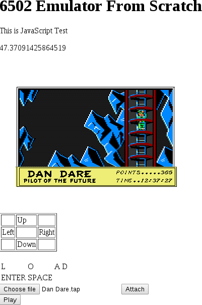
With the bugs fixed mentioned in this blog, Dan Dare is now in a fully playable state. Here is a couple of screen shots:


You will remember that in one of my previous I mentioned the use of github io pages, where you can serve your git pages as a website.

Just to refresh your mind, the github io page I have creataed for this series of blogs was ovalcode.github.io

I haven't updated this io page for some time until this blog post. So, you can now play with my JavaScript emulator without cloning the source and starting a web server.

As an added bonus, I have added some functionality to this io page which will allow you to use the emulator on a touch device like a tablet. This include just enough letters enabling you to kick off the loading of a tape image. This will however be slow on a mobile device than on an actual PC.

To give you an idea of the speed, I have added a frame per second counter on top of screen of the emulator. On a Intel i7 I managed to get about the real speed of 50 frames per second.

On an Intel i3 and i5 I get between 40 and 45 frames per second.

The best I could get on a mobile device was 9 frames per second.

In Summary


This blog was the concluding post on my series of blog posts on writing a JavaScript emulator from scratch.

In this blog we implemented sprites and ended off with our emulator been able to fully play Dan Dare.

Thanks for everyone that read my series of blog posts.

I am thinking of writing a similar set of blog posts in a couple of months time, where I will be implementing an emulator on Android.

Take care!

Wednesday 27 July 2016

Part 20: Debbuging the garbled game screen

Foreword

In the previous blog we added joystick emulation to our emulator and managed to start the game.

However, with the start of the game we were faced with a garbled screen.
In this blog we will investigate why we are presented with a garbled screen.

I will using an interesting debugging technique where we will compare the state of our emulator with the state of another known working emulator in order to isolate the issue in our emulator.

This is a bit of a lengthy blog, so maybe have a cup of coffee handy when reading :-)

Enjoy!

Initial round of debugging

Let us do an initial round of debugging to get some pointers into which direction we should go to find out why the game screen is garbled.

Let us have a look again at the problem screen of the previous blog:

We haven't got a change to properly test the multicolor text mode that we have implemented in a previous blog. Could it be that there is still some bugs in that functionality causing this rendering issues?

A quick sanity check for this is to inspect the screen character memory. There is something concrete we can look for, for the instance the out of place A in the top right corner. If we get that character in the same position in character memory, we know that our theory on a rendering bug in the multicolor text mode doesn't carry much weight.

From the looks of it we can see that the characters displayed is definitely custom defined characters and we are not guaranteed that it use standard PET screen codes. To get an idea what screen codes it is using, we can look at a sequence of screen characters, like DAN LANDED THE ANASTASIA.

The above mentioned sequence of screen codes is more less at the beginning of the second screen line.

So lets do some memory inspection:

 The second screen line starts at memory location 427h. We see they are using code A0 for a space and 81 for an A. From that point they use the ordinal position in the alphabet. So, the characters 84 81 8E A0 8C 81 8E 84 85 84 corresponds to DAN LANDED.

The out of place A is at the end of the second line which is at location 44E. Indeed, the code at that location is 81, which is an A!

So, something in the machine code program is populating the screen RAM incorrectly, but what?

At this point it would be really useful to do some comparisons against a second emulator that does render this screen correctly. The emulator I am going to use for this purpose will be VICE.

VICE by the way, gives you some nice debugging facilities. One of these facilities is that it allows you to break when the contents of a specific memory location change.

Fire up the loading of Dan Dare in Vice. As soon as the intro screen appears, hit ALT+H to activate the monitor.


Time to set a breakpoint. We would like to break as soon as an instruction writes to location 427. So enter the following in the monitor:

watch store 427

The monitor will give you a confirmation that the breakpoint is set. Enter goto to resume the emulator:


Now hit the firebutton to start the game. Your breakpoint will trigger in a flash of a second.

We know single step s couple of times to determine where the data comes from which is populated to the screen:

Looks like we hit a loop that is busy clearing the screen. Not exactly what we are looking for. So, type in goto to resume the emulator.

After a flash, our breakpoint gets triggered again. So lets single step a couple of times again.

This time it looks more promising:


Looks like it is literally copying data from the location 1C00. So lets us inspect this memory area. In the Vice Monitor you just need to issue m 1c00 to inspect this area:


And indeed, at memory location 1c27, we can make out the familiar DAN DARE LANDED THE ANASTASIA.

So, what populates the memory area at 1C00? To answer this question, we need to follow the above mentioned debug process, but with watch point at address 1C00.

Restarting the debug process with the new watch point will again break in loop filling the area with the value 20. So give it another goto.

When it breaks again, we give it a couple of single steps, yielding the following screen:


So, it retrieves the data via stored address at $96 and store the data via address stored at A8.

I think next we should determine what manipulate the contents of address $96. This yield the following:


I think this is a nice point to actually compare with our JavaScript emulator to see if our emulator comes up with the same register values when address 5358 is hit the first time.

Just to make sure we are not chasing out own tale, I have restarted the Vice emulator 3 times hitting breakpoint 5358 each time and verify that the register values is the same each time.

We start our JavaScript emulator with a breakpoint at 5358. When it hits this our breakpoint, our register values is a follows:

Acc:40 X:ae Y:02SP: f1 PC:5358 Z:0 N:0 C:0 V:0 D:0

Register X is clearly different!

It would be nice if we could go back to previous instructions executed to see where the world went pair shape.

In the next two sections I will show how to setup Vice and our JavaScript emulator respectively to log the state of each instructions executed. We can then do some comparisons against the two logs to see where we went wrong.

Enabling Instruction tracing in Vice

As mentioned in the previous section, it would be nice if we could log the state of the registers after each and every instruction execution.

How do you enable this in Vice? Reading through the documentation of Vice and consulting web resources is not very explicit about such a kind of functionality.

However, if you browse the source code of Vice, you do in fact see debug logging statements after executing a 6502 instruction.

So, it looks like the functionality that we want is within Vice. It is just a matter of knowing how to enable it.

After some further investigations I found that one is out of luck with pre-compiled Vice binaries. However, if you compile Vice yourself, your luck is in :-)

Ok, I am going to make one assumption at this point, and this is that you do have a workable environment for building Vice from source. Typically for a Debian/Ubuntu environment this would mean having installed the build-essential package, together with some GUI libraries like GTK2 development library.

Now, if you open up a terminal window, navigate to the Vice source and type:

./configure -help

You will see that one of the options is --enable-debug-code

This is the option we are looking for, so run configure with the following options:

./configure --enable-debug-code --enable-gnomeui

The --enable-gnomeui  option compiles your version of Vice with Gnome support, suitable for Debian/Ubuntu.

Kick off the building of Vice with:

make

We will not bother to install this version of Vice, since it is a debug version anyway. So, after the make process is finished, just navigate to the src folder and kick off the emulator with:

./x64


On startup, you might get some warning messages that the sound system could not be started. Not a problem in our scenario.

You will notice an extra menu category Debug in the Vice window:

In this category, the menu item of interest is Main CPU Trace. When you select this menu item, you will see the terminal window from which you invoked Vice will get cluttered with log items:

The most left hand column is the address, and the column on the right hand side is the status of the registers in the following order: Accumulator, X register, Y register and SP.

Typically your terminal window is limited by the number of lines it can store in the scroll back history, so it would be better to log the trace the a file to avoid possible loss of lines.

The following command will enable logging to a file for you:

./x64 -logfile log.txt

This will log console output to the file log.txt.

One thing that you will notice when you enable this logging, is that the performance of the emulator drop dramatically. On my desktop it performs at about 6% of the original speed. So it is advisable to only switch on logging at the point you need it. Luckily you can toggle this logging on and off while the emulator is running.

Enabling Instruction tracing for our Emulator

For our JavaScript Emulator we would like to enable the same kind of logging as we did for Vice in the previous section.

We already have two methods in emulator that will provide you a string representation of the state of the registers and the current instruction disassembled. So the only thing you need to do is to write these values with to write these values to the console with console.log.

In the previous section we learned an important lesson. This kind of logging slow down the emulator dramatically. We cannot bargain that our emulator would perform any better, so we also need to built in a functionality that you can enable/disable this logging at any time.

So, let us start by adding a checkbox to our index page for enabling/disabling logging.

<input type="file" id="file" name="myfile"/>
<button onclick="myTape.attachTape(document.getElementById('file').files[0])">Attach</button>
<br/>
<button onclick="mymem.togglePlayPresed()">Play</button>
<br/>
<input type="checkbox" id="allowDebug"/> Allow logging<br/>
<textarea id="registers" name="reg" rows="1" cols="60"></textarea>
<br/>
<textarea id="memory" name="mem" rows="15" cols="60"></textarea>
From Location:
<input type="text" id="frommem">
<button onclick="showMem()">Refresh Dump</button>
<br/>


Next, we add a property to our Cpu class for indicating whether logging is on or off:

function cpu(memory) {
...
  var allowLogging = false;
...
  this.setAllowLogging = function(flag) {
    allowLogging = flag;
  }
...
}

Next we need to add a check in the runBatch method that will check whether the checkbox is checked and set the applicable property in the cpu class.

      function runBatch() {
        if (!running)
          return;
        mycpu.setAllowLogging(document.getElementById("allowDebug").checked);
        while (true) { 
        ...
        }
        ...
      }

Next, we need add the method log_debug within the Cpu class, that will only log if logging is enabled:

  function log_debug(value) {
    if (allowLogging) {
      console.log(value);
    }
  }


And, we need to use this method within the step method:

  this.step = function () {
    log_debug(this.getDecodedStr() + "  " + this.getDebugReg());
    if ((myInterruptController.getCpuInterruptOcurred() | myvideo.vicIntOccured()) & (interruptflag == 0)) {
    ...
    }
    ...
  }

Now let us take this new functionality for a test drive. I was testing this functionality within the Google Chrome browser. To see the console it import that you have the Inspect an element view open. In Google Chrome you enable this view with Cntrl+Shift+I.


One thing I should mention is that Google console also have a limit on the number of lines it can display. We can also get around this limitation by enable file logging by starting chrome from the command line in the following way:

google-chrome --enable-logging

This create a file called chrome_debug.log in some folder in you user directory. The specific folder for this file differs from platform to platform. In Linux, you will find this file in the folder ~/.config/google-chrome.

So, in short, the file chrome_debug.log will contain  the un-truncated version for our instruction state logging for our JavaScript emulator.

Reconciling the two logs

With the logging capability added to both Vice and our emulator in the previous two sections, it is time we create a log for both systems doing the same action.

Do the following on both systems, and keep the logs:


  • Start off the loading of Dan Dare
  • Once you see the intro screen, enable logging
  • Press and hold the firebutton, until you see the game has started
  • Stop logging
In this section we will use our Vice log for reference and refer to our emulator log when necessary.

In the initial round of debugging we decided that the starting point for our debugging should be address

5358.

So within the Vice log search for .5358:


This log allows us to trace back to determine where register X got its value from. And we see the X register got its value from memory location AA.

So, what populated location AA? To answer this search for $AA:


And we spot the place where the initial value is assigned to memory location $AA.

Let us pause for a moment and compare the same snippet with the log of our own emulator:


If you compare the logs you will actually see that the register states are in sync between the two logs till it hits the instruction at 5343, which is LDA($aa),y

You might have a moment of despair, thinking: Know we need to do a similar exercise to find what is populating the effective address of ($aa),y

But, hang on, we are almost at the root of the problem. The effective address of ($aa), y is B000. What is special about the address B000? It falls within the address space of basic ROM! This screams: Bank switching!

And in fact, we haven't implemented bank switching of the Basic ROM within our emulator.

Well, I fully agree, we could have avoided this ugly detour by implementing all bank switching at once when we were busy implementing bank switching for the KERNEL ROM. But, I thought this is a nice debugging technique to use, should hit a brickwall.

Implementing Basic Bank Switching

Let us implement bank switching for the Basic ROM.

First we create a method within the memory class that tell if the Basic ROM is visible by looking at memory location 1:

  function basicEnabled() {
    temp = mainMem[1] & 3;
    return (temp == 3);
  }


Next, we should modify the readMem function:

  this.readMem = function (address) {
    if ((address >= 0xa000) & (address <=0xbfff) & basicEnabled())
      return basicRom[address & 0x1fff];
    else if ((address >= 0xe000) & (address <=0xffff) & kernelEnabled())
      return kernalRom[address & 0x1fff];
    else if ((address >= 0xd000) & (address <= 0xdfff) & IOEnabled()) {
      return IORead(address);
    } else if (address == 1) {
      var temp = mainMem[address] & 239;
      if (!playPressed)
        temp = temp | 16;
      return temp;
    }
    return mainMem[address];
  }


With all this changes let us give out emulator a test run again:


It already looks better, although Dan is still missing and something is wrong with the colors. We will cover these issues in the next blog.

In Summary

In this blog we fixed the garbled screen we were presented with when starting the game.

In the debugging process we used a technique where we compared the state of our emulator with the state of another emulator which renders the screen in question correctly.

In the next blog we will be fixing the remaining rendering issues like invisible Dan Dare, and the invisible Treen.

Till next Time!


Saturday 23 July 2016

Part 19: Emulating the joystick

Foreword

In the previous blog we fixed the intro screen.

In this blog we will implement joystick emulation and see till which point the game will start up when we hit the fire button.

Implementing Joystick emulation

In the previous blog we covered the theory of a joystick interfaces to the C64.

We can therefore go straight ahead and start to implement joystick emulation to our emulator.


The joystick emulation in our emulator will also be interfacing with the keyboard, so we can utilise the keyboard class for joystick emulation.

So, which keys on the keyboard will we be using for the joystick? I was thinking to use the cursor keys on the numpad and Numpad zero for the fire button. To operate the joystick, Numlock should be off.

You may remember that the keyboard class maintains an array of which keys are hold down at any instance. We can also use this array to store joystick keys that are down. It is important though that the main keyboard emulation functionality should ignore these keys.

To ignore these keys we should add a default selector to the switch statement of the getScanCode method:

  function getScanCode(chr) {
    switch (chr) {
      case KEY_A:
        return 10;
      break;
      case KEY_B:
        return 28;
      break;
      case KEY_C:
        return 20;
      break;
      case KEY_D:
        return 18;

...
      case KEY_6:
        return 19;
      break;
      case KEY_7:
        return 24;
      break;
      case KEY_8:
        return 27;
      break;
      case KEY_9:
        return 32;
      break;
      default: return -1;

    }
    
  }


This default selector has the effect that for all joystick keys a -1 will be returned.

getColumnByte should then check for this -1 value and ignore if it is the case:

  this.getColumnByte = function(rowByte) {
    var rowArray = [0,0,0,0,0,0,0,0];
    rowByte = ~rowByte;
    rowByte = rowByte & 0xff;
    var i;
    for (i = 0; i < keyarray.length; i++) {
      var scanCode = getScanCode(keyarray[i]);
      var rowNum = (scanCode & 0x38) >> 3;
      if (scanCode != -1) {
        rowArray[rowNum] = rowArray[rowNum] | (1 << (scanCode & 7));
      }
    }

    ...

  }

Our joystick keys will now be ignored by our main keyboard emulation functionality.

We should now add a method that returns the joystick byte when CIA#1 register is read:

  this.getJoyStickByte = function () {
    var result = 0;
    for (i = 0; i < keyarray.length; i++) {
      var temp = keyarray[i];
      switch (temp) {
        //left
        case 37:
          result = result | 4;
        break;
        //right
        case 39:
          result = result | 8;
        break;
        //up
        case 38:
          result = result | 1;
        break;
        //down
        case 40:
          result = result | 2;
        break;
        //fire
        case 45:
          result = result | 16;
        break;
      }
    }
    return result;
  }


Our Memory class should invoke this method at the correct moment:

  function ciaRead(address) {
    if (address == 0xdc00) {
      return (~keyboardInstance.getJoyStickByte()) & 0xff;
    } else if (address == 0xdc01) {
      return keyboardInstance.getColumnByte(mainMem[0xdc00]);
    } else if (address == 0xdc04) {
      return mytimerA.getTimerLow();
    } else if (address == 0xdc05) {
      return mytimerA.getTimerHigh();
    } else if (address == 0xdc06) {
      return mytimerB.getTimerLow();
    } else if (address == 0xdc07) {
      return mytimerB.getTimerHigh();
    } else if (address == 0xdc0d) {
      return myinterruptController.getInterrupts();
    } else if (address == 0xdc0e) {
      return mytimerA.getControlRegister();
    } else if (address == 0xdc0f) {
      return mytimerB.getControlRegister();
    } else {
      return mainMem[address];
    }

  }

That was relatively painless!

Lets take our emulator for a test drive with these changes.

With the intro screen showing, lets hit the fire button, aka numpad 0. We can see that the game started, but we are presented again with the garbled screen that we briefly saw in the previous blog:


Some closer investigation of the VIC registers revealed that raster interrupts is enabled when this screen is shown.

We haven't enabled rasterline interrupts as yet within our emulator, but in the next section we will do that.

Implementing raster interrupts

Lets start coding the raster interrupts.

First, we implement the following methods:

...
  function rasterIntEnabled() {
    return (registers[0x1a] & 1) == 1;
  }

  function targetRasterReached() {
    var temp = registers[0x11] & 0x80;
    temp = temp << 1;
    temp = temp | (registers[0x12]);
    var tempCurrentLine = (cycleline == 312) ? 0 : cycleline;
    return (temp == tempCurrentLine);
  }
...

The first method determines if raster interrupts is enabled and the second method determines if the target raster line is reached yet. The target raster line is stored in register 12h and bit 7 of register 11h.

Something that might need some explanation is the check for 312 in the targetRasterReached method. Raster lines are within the range 0 to 311. At some point when this method gets called the raster line might be 312, e.g. roll over to 0 not yet applied. This line of code just caters for this condition.

Now, both these methods needs to be called in the processPixels method:

  this.processpixels = function() {
      ...
      if (cycleInLine > 63) {
        cycleInLine = 0;
        cycleline++;
        if (targetRasterReached() & rasterIntEnabled()) {
          registers[0x19] = registers[0x19] | 1 | 128;
        }
        updateCharPos();
      }
      ...
  }

So, if an interrupt occurred the applicable bit within register 19h is set.

With this code implemented, machine code polling the VIC interrupt register to see if a raster interrupt occurred would work correctly. However, at this point in time we would not be able to physically interrupt our emulated CPU with a raster interrupt.

We need to add some functionality to our CPU class to check during each call to step whether a raster interrupt occurred. This require us to also inject the Video class into our video class as a dependency. So lets add property and a setter for a video class into our cpu class:

function cpu(memory) {

...
 var myvideo;
...
  this.setVideo = function (video) {
    myvideo = video;
  }
...

}

We will let the index page handle the dependency injection for us:

      ...
      var mycpu = new cpu(mymem);
      myAlarmManager.setCpu(mycpu);
      myInterruptController.setCpu(mycpu);
      mycpu.setInterruptController(myInterruptController);
      var myvideo = new video(document.getElementById("screen"), mymem, mycpu);
      mymem.setVideo(myvideo);
      mycpu.setVideo(myvideo);
      ...

So far, so good. Next we need to add a method to out video class which will indicate for our Cpu whether an raster interrupt has occurred:

  this.vicIntOccured = function() {
    return registers[0x19] >= 128;
  }

Our Cpu needs to invoke this method:

function cpu(memory) {

...
  this.step = function () {
    if ((myInterruptController.getCpuInterruptOcurred() | myvideo.vicIntOccured()) & (interruptflag == 0)) {
        interruptOcurred = 0;
        Push(pc >> 8);
        Push(pc & 0xff);
        breakflag = 0;
        Push(getStatusFlagsAsByte());
        breakflag = 1;
        interruptflag = 1;
        tempVal = localMem.readMem(0xffff) * 256;
        tempVal = tempVal + localMem.readMem(0xfffe);
        pc = tempVal;
    }
...

}

We are almost done. We need to, however, give some attention attention to interrupt acknowledgement on the VIC side, very similar to what we have done in previous blogs with the CIA chip.

The interrupt acknowledge mechanism works a bit different in the VIC than in a CIA chip.

If you don't acknowledge interrupts on a CIA, your CPU will not receive new IRQ's.

The VIC works the the opposite. If you don't acknowledge an interrupt on the VIC, it will keep interrupting the CPU each time you clear the Interrupt disable flag.

Also, on the VIC, to acknowledge an intergroup you need  to write a 1 to the applicable bit in register 19.

With all this changes our writeReg method looks as follows:

  this.writeReg = function (number, value) {
    if (number == 0x19) {
      var temp = ~value & registers[number];
      temp = temp & 0xf;
      registers[number] = (temp > 0) ? (temp | 128) : 0;
    } else {
      registers[number] = value;
    }
  }

Before we take our emulator for a test drive there is just one more hack we should remove:

      function runBatch() {
        if (!running)
          return;
        //myvideo.updateCanvas();
        //var targetCycleCount =  mycpu.getCycleCount() + 20000;
        while (true) { 
          mycpu.step();
          myAlarmManager.processAlarms();
          //if (mycpu.getCycleCount() > 6000000)            
          //  mymem.setSimulateKeypress();
          //var blankingPeriodLow = targetCycleCount - 100;
          //if (myvideo.getCurrentLine() > 284) {
          //  mymem.writeMem(0xD012, 0);
          //} else  {
          //  mymem.writeMem(0xD012, 1);
          //}          if (mycpu.getPc() == breakpoint) {
            stopEm();
            return;
          }
          var framefinished = myvideo.processpixels();
          if (framefinished)            
            return;
        }
        //mycpu.setInterrupt();
      }

This hack stems from the early life of our emulator.

Lets us start our emulator again. This time, the screen looks better:


The majority of the screen is still garbled, but at least is the statusbar visible and the time updating every second.

Lets see what happens when we move around wit the the left/right arrows keys.

There is definitely some movement, and although we cannot see Dan Dare, we can see a battle with a Treen:


We will fix these remaining issues in the next blog or two.

In Summary

In this blog we implemented joystick emulation enabling us to start the game.

There is still a number of issues with rendering the graphic of the game.

We managed to fix the status bar and perfom some basic moves with the joystick.

In the next blog we investigate why the rest of the screen is garbled.

Monday 18 July 2016

Part 18: Fixing Intro Screen

Foreword

In the previous blog we managed to successfully load the game Dan Dare, but ended up with a garbled intro screen.

In this blog we will investigate why the intro screen shows garbled and fix it.

Investigating the garbled intro screen

Lets start off by investigating why the intro screen looks garbled.

There is some random alpha numeric characters on the screen, suggesting that a custom character set is defined. We know for a fact that we haven't implemented custom characters yet in our emulator.

Let us do a quick refresher on how custom character sets work on the C64.

The VIC-II chip gives you the capability to specify different base locations in memory for the screen character memory and for the character set images. You configure the base addresses via location D018 and DD00. Location DD00 provides you with most significant two bits base address.

Something interesting about the character base addresses is that if it falls within the region 1000h-1fffh or 9000-9fffh in memory, then the VIC-II will read the character info from the character ROM. For all other regions the VIC-II will retrieve the info from RAM.

So, in a nutshell, if you set the character base address, avoiding above mentioned regions, you can define your own character set. Ok, it goes without saying that you actually need to write your character data at the specified base address.

Back to our problem. Lets do some memory inspection to determine the character base address. The inspection gives us the following:
  • Memory location D018: 14
  • Memory location DD00: 17
This translates to base address 1000h, which is in the character ROM space. So, we are actually back to square 1.

For another clue, lets stop the emulator and do some single stepping. Maybe we can see something interesting.

And, indeed there is something interesting:
5876 LDA $d012
5879 CMP #$d2
587b BNE $5876

The emulator is stuck in this loop. Keep checking till rasterline d2 arrives.
Currently  the VIC registers just map to plain RAM registers in our emulator. So reading D012 will keep returning the same result.

It is time we hook up the VIC-II registers to the Video class so we can get some sensitible values when a program reads them.


From our discussion so far, we have a number of things to do in this bog. Lets quickly create a short list:
  • Make Video class responsible for working with VIC-II register memory accesses
  • Change memory class to delegate read/write requests for VICII registers to the Video class
  • Assign a similar responsibility for the Video class regarding the color memory
  • Add a method to the memory class that the video class can call for memory access. This method should closely model the VIC-II memory model. This method should have the following properties:
    • Accept a 14 address
    • Create an effective memory address via location DD00
    • If the effective address is within the range 1000-1fff or 9000-9fff return data to the video class from the character ROM
    • If the effective address is not within above mentioned region return requested contents from the main memory.
The last heading in the short list is necessary because of luring custom character sets.

Tasking Video class with VICII register access

We have decided that VIC II register a should be the responsibility of the video class. There are 46 VIC registers, so lets start with defining a local array within the video class containing 46 elements, with accompanied getters and setters:

function video(mycanvas, mem, cpu) {
...
 var registers = new Uint8Array(0x2e);
...
  this.writeReg = function (number, value) {
    registers[number] = value;
  }

  this.readReg = function (number) {
    return registers[number];
  }
...
}

Lets do the same exercise for the colorRAM:

function video(mycanvas, mem, cpu) {
...
  var colorRAM = new Uint8Array(1000);
...
  this.writeColorRAM = function(number, value) {
    colorRAM[number] = value;
  }

  this.readColorRAM = function(number) {
    return colorRAM[number];
  }...
}

We need to add some functionality when reading D012 to retrieve current raster line number:

  this.readReg = function (number) {
    if (number == 0x11) {
      var bit8 = (cycleline & 0x100) >> 1;
      var temp = (registers[number] & 0x7f) | bit8;
      return temp;
    } else if (number == 0x12) {
      return (cycleline & 0xff);    } else {
      return registers[number];
    }
  }

You will notice that I have also included an entry for location D011. D011 contains the ninth bit of the raster counter.

We now need to change the Video class so that its internal operations also make use of the internal registers:

function video(mycanvas, mem, cpu) {
...
  function displayEnabled() {
    return ((registers[0x11] & 0x10) != 0)
  }
...
  function drawCharline() {
    var bitmapMode = ((registers[0x11] & 0x20) != 0) ? 1 : 0;
    var multicolorMode = ((registers[0x16] & 0x10) != 0) ? 1 : 0;    var screenMode = (multicolorMode << 1) | bitmapMode;
    switch (screenMode) {
      //text mode, normal
      case 0:
        drawTextModeNormal(charPosInMem + cycleInLine - 5);
      break;

      //bitmap mode, normal
      case 1:
      break;
      
      //text mode, multi color
      case 2:
      break;

      //bitmap mode, multi color
      case 3:
        drawBitmapModeMultiColor(charPosInMem + cycleInLine - 5);
      break;
    }
  }

  function drawTextModeNormal(charPos) {
    var screenCode = localMem.readMem(1024 + charPos);
    var currentLine = localMem.readCharRom((screenCode << 3) + ((cycleline - 42) & 7));
    var textColor = colorRAM[charPos] & 0xf;
    var backgroundColor = registers[0x21] & 0xf;    var currentCol = 0;
    for (currentCol = 0; currentCol < 8; currentCol++) {
      var pixelSet = (currentLine & 0x80) == 0x80;
      if (pixelSet) {
        imgData.data[posInCanvas + 0] = colors[textColor][0];
        imgData.data[posInCanvas + 1] = colors[textColor][1];
        imgData.data[posInCanvas + 2] = colors[textColor][2];
        imgData.data[posInCanvas + 3] = 255;
      } else {
        imgData.data[posInCanvas + 0] = colors[backgroundColor][0];
        imgData.data[posInCanvas + 1] = colors[backgroundColor][1];
        imgData.data[posInCanvas + 2] = colors[backgroundColor][2];
        imgData.data[posInCanvas + 3] = 255;
      }
      currentLine = currentLine << 1;
      posInCanvas = posInCanvas + 4;
   }

  }

  function drawBitmapModeMultiColor(charPos) {
    var currentLine = localMem.readMem(0xe000+(charPos << 3) + ((cycleline - 42) & 7));
    var textColor = colorRAM[charPos];
    var backgroundColor = registers[0x21];    var color1 = (localMem.readMem(49152 + charPos) & 0xf0) >> 4;
    var color2 = localMem.readMem(49152 + charPos) & 0xf;
    var color3 = colorRAM[charPos] & 0xf;
    var colorArray = [backgroundColor, color1, color2, color3];
    var pixPair = 0;
    for (pixPair = 0; pixPair < 4; pixPair++) {
      var colorValue = (currentLine >> 6) & 3;
      imgData.data[posInCanvas + 0] = colors[colorArray[colorValue]][0];
      imgData.data[posInCanvas + 1] = colors[colorArray[colorValue]][1];
      imgData.data[posInCanvas + 2] = colors[colorArray[colorValue]][2];
      imgData.data[posInCanvas + 3] = 255;
      imgData.data[posInCanvas + 4] = colors[colorArray[colorValue]][0];
      imgData.data[posInCanvas + 5] = colors[colorArray[colorValue]][1];
      imgData.data[posInCanvas + 6] = colors[colorArray[colorValue]][2];
      imgData.data[posInCanvas + 7] = 255;

      currentLine = currentLine << 2;
      posInCanvas = posInCanvas + 8;
   }

  }


  function fillBorderColor() {
    var borderColor = registers[0x20] & 0xf;
    var i;
    for (i = 0; i < 8; i++ ) {
      imgData.data[posInCanvas + 0] = colors[borderColor][0];
      imgData.data[posInCanvas + 1] = colors[borderColor][1];
      imgData.data[posInCanvas + 2] = colors[borderColor][2];
      imgData.data[posInCanvas + 3] = 255;
      posInCanvas = posInCanvas + 4;
    }

  }
...
}


We know need to modify the Memory class to use the Video class for VIC register accesses. It would probably make sense to add another statement to the nested if statement of readMem and writeMem. But, we already have IO region related entry for CIA access. I think it would look less clunky if we collate all IO region access into a mthod of its own.

With this in mind, our readMem and writeMem method will look as follows:

  this.readMem = function (address) {
    if ((address >= 0xa000) & (address <=0xbfff))
      return basicRom[address & 0x1fff];
    else if ((address >= 0xe000) & (address <=0xffff) & kernelEnabled())
      return kernalRom[address & 0x1fff];
    else if ((address >= 0xd000) & (address <= 0xdfff) & IOEnabled()) {
      return IORead(address);
    } else if (address == 1) {
      var temp = mainMem[address] & 239;
      if (!playPressed)
        temp = temp | 16;
      return temp;
    }
    return mainMem[address];
  }

  this.writeMem = function (address, byteval) {
    if ((address >= 0xd000) & (address <= 0xdfff) & IOEnabled()) {
      IOWrite(address, byteval);
      return;
    } else if (address == 1) {
      var temp = byteval & 32;
      temp = temp >> 5;
      tape.setMotorOn(temp);
    }   
    mainMem[address] = byteval;
  }

The IORead and IOWrite methods look as follows:

  function IORead(address) {
    if ((address >= 0xdc00) & (address <= 0xdcff)) {
      return ciaRead(address);
    } else if ((address >= 0xd000) & (address <= 0xd02e)) {
      return myVideo.readReg(address - 0xd000);
    } else if ((address >= 0xd800) & (address <= 0xdbe8)) {
      return myVideo.readColorRAM (address - 0xd800);
    } else {
      return IOUnclaimed[address - 0xd000];
    } 
  }

  function IOWrite(address, value) {
    if ((address >= 0xdc00) & (address <= 0xdcff)) {
      return ciaWrite(address, value);
    } else if ((address >= 0xd000) & (address <= 0xd02e)) {
      return myVideo.writeReg(address - 0xd000, value);
    } else if ((address >= 0xd800) & (address <= 0xdbe8)) {
      return myVideo.writeColorRAM (address - 0xd800, value);
    } else {
      IOUnclaimed[address - 0xd000] = value;
      return;
    } 
  }

You will see in this code the use of an array called IOUnclaimed. This is for IO devices that we haven't implemented yet like CIA2 and SID. This just to encapsulate the block switch in/out functionality for the IO region. For completeness, let me show the declaration of the IOUnclaimed array:

..
 var IOUnclaimed = new Uint8Array(4096);
...

The Memory class is now dependant on the Video class, so we need to add a setter in the memory class:

  this.setVideo = function(video) {
    myVideo = video;
  }

This setter needs to be called by the index page during initialisation just after the a video instance is created:

...
      var myvideo = new video(document.getElementById("screen"), mymem, mycpu);
      mymem.setVideo(myvideo);
...

VIC II memory accesses

We now need to add a method to the memory class that the video class can call for memory access. This method will comply to the VIC-II memory model.

Here is the code for that method:

  this.vicRead = function(address) {
    var topBits = IOUnclaimed[0xd00] & 3;
    topBits = 3 - topBits;
    var effectiveAddress = (topBits << 14) | address;
    if ((effectiveAddress >= 0x9000) & (effectiveAddress < 0xa000)) {
      effectiveAddress = effectiveAddress & 0xfff;
      return charRom[effectiveAddress];
    } else if ((effectiveAddress >= 0x1000) & (effectiveAddress < 0x2000)) {
      effectiveAddress = effectiveAddress & 0xfff;
      return charRom[effectiveAddress];
    } else {
      return mainMem[effectiveAddress];
    }
  }


This method gets bits 14 and 15 of the effective address from location DD00. It also reads the requested from character ROM if the effective address is within the range 1000-1fff or 9000-9fff.

We now need to modify the video class to use the method vicRead:

  function drawTextModeNormal(charPos) {
    var baseCharAdd = (registers[0x18] >> 1) & 7;    
    baseCharAdd = baseCharAdd << 11;    
    var baseScreenAdd = (registers[0x18] >> 4) & 0xf;    
    baseScreenAdd = baseScreenAdd << 10;    
    var screenCode = localMem.vicRead(baseScreenAdd + charPos);
    var currentLine = localMem.vicRead(baseCharAdd + (screenCode << 3) + ((cycleline - 42) & 7));    var textColor = colorRAM[charPos] & 0xf;
    var backgroundColor = registers[0x21] & 0xf;
    var currentCol = 0;
    for (currentCol = 0; currentCol < 8; currentCol++) {
      var pixelSet = (currentLine & 0x80) == 0x80;
      if (pixelSet) {
        imgData.data[posInCanvas + 0] = colors[textColor][0];
        imgData.data[posInCanvas + 1] = colors[textColor][1];
        imgData.data[posInCanvas + 2] = colors[textColor][2];
        imgData.data[posInCanvas + 3] = 255;
      } else {
        imgData.data[posInCanvas + 0] = colors[backgroundColor][0];
        imgData.data[posInCanvas + 1] = colors[backgroundColor][1];
        imgData.data[posInCanvas + 2] = colors[backgroundColor][2];
        imgData.data[posInCanvas + 3] = 255;
      }
      currentLine = currentLine << 1;
      posInCanvas = posInCanvas + 4;
   }

  }

  function drawBitmapModeMultiColor(charPos) {
    var baseCharAdd = (registers[0x18] >> 1) & 7;    
    baseCharAdd = baseCharAdd << 11;    
    var baseScreenAdd = (registers[0x18] >> 4) & 0xf;    
    baseScreenAdd = baseScreenAdd << 10;    
    var currentLine = localMem.vicRead(baseCharAdd+(charPos << 3) + ((cycleline - 42) & 7));    var textColor = colorRAM[charPos];
    var backgroundColor = registers[0x21];
    var color1 = (localMem.vicRead(baseScreenAdd + charPos) & 0xf0) >> 4;
    var color2 = localMem.vicRead(baseScreenAdd + charPos) & 0xf;    var color3 = colorRAM[charPos] & 0xf;
    var colorArray = [backgroundColor, color1, color2, color3];
    var pixPair = 0;
    for (pixPair = 0; pixPair < 4; pixPair++) {
      var colorValue = (currentLine >> 6) & 3;
      imgData.data[posInCanvas + 0] = colors[colorArray[colorValue]][0];
      imgData.data[posInCanvas + 1] = colors[colorArray[colorValue]][1];
      imgData.data[posInCanvas + 2] = colors[colorArray[colorValue]][2];
      imgData.data[posInCanvas + 3] = 255;
      imgData.data[posInCanvas + 4] = colors[colorArray[colorValue]][0];
      imgData.data[posInCanvas + 5] = colors[colorArray[colorValue]][1];
      imgData.data[posInCanvas + 6] = colors[colorArray[colorValue]][2];
      imgData.data[posInCanvas + 7] = 255;

      currentLine = currentLine << 2;
      posInCanvas = posInCanvas + 8;
   }

  }

A Test Run

With all these changes, lets do a test run.

The emulator didn't start so well:

Some closer investigation revealed that the problem is caused by the 6510 CPU register at memory location 1.

At startup I assign a value of 3. This is sufficient to ensure that your system boots, but it disables the IO Region. This has the effect that the IO register  at location DD00 misses the write from the CPU, so the Video class gets its data from the wrong bank.

We obviously got away with this previously because we haven't implemented complete bank switching of the IO region. All IO writes/reads went straight to the main memory.

A save value to write to memory location 1 at startup is ffh. So, lets adjust this value and restart the emulator.

This time the world is back to normal. So, lets start loading Dan Dare and see how far our emulator can get this time.

This time around the intro screen is just a blank screen.

Some investigation revealed that something switched to multicolor text mode. This is puzzling, but lets anyway implement multi color text mode in the video class.

First we create a method within the Video class for the functionality:

  function drawTextModeMultiColor(charPos) {
    var baseCharAdd = (registers[0x18] >> 1) & 7;
    baseCharAdd = baseCharAdd << 11;
    var baseScreenAdd = (registers[0x18] >> 4) & 0xf;
    baseScreenAdd = baseScreenAdd << 10;
    var screenCode = localMem.vicRead(baseScreenAdd + charPos);
    var currentLine = localMem.vicRead(baseCharAdd + (screenCode << 3) + ((cycleline - 42) & 7));
    var textColor = colorRAM[charPos] & 0xf;
    if ((textColor & 8) == 0)
      return drawTextModeNormal(charPos);
    var backgroundColor = registers[0x21];
    var color1 = registers[0x22];
    var color2 = registers[0x23];
    var color3 = textColor;
    var colorArray = [backgroundColor, color1, color2, color3];
    var pixPair = 0;
    for (pixPair = 0; pixPair < 4; pixPair++) {
      var colorValue = (currentLine >> 6) & 3;
      imgData.data[posInCanvas + 0] = colors[colorArray[colorValue]][0];
      imgData.data[posInCanvas + 1] = colors[colorArray[colorValue]][1];
      imgData.data[posInCanvas + 2] = colors[colorArray[colorValue]][2];
      imgData.data[posInCanvas + 3] = 255;
      imgData.data[posInCanvas + 4] = colors[colorArray[colorValue]][0];
      imgData.data[posInCanvas + 5] = colors[colorArray[colorValue]][1];
      imgData.data[posInCanvas + 6] = colors[colorArray[colorValue]][2];
      imgData.data[posInCanvas + 7] = 255;

      currentLine = currentLine << 2;
      posInCanvas = posInCanvas + 8;
   }
  }

Then we add an item to the color mode switch selector:

  function drawCharline() {
    var bitmapMode = ((registers[0x11] & 0x20) != 0) ? 1 : 0;
    var multicolorMode = ((registers[0x16] & 0x10) != 0) ? 1 : 0;
    var screenMode = (multicolorMode << 1) | bitmapMode;
    switch (screenMode) {
      //text mode, normal
      case 0:
        drawTextModeNormal(charPosInMem + cycleInLine - 5);
      break;

      //bitmap mode, normal
      case 1:
      break;
      
      //text mode, multi color
      case 2:
         drawTextModeMultiColor(charPosInMem + cycleInLine - 5);
      break;

      //bitmap mode, multi color
      case 3:
        drawBitmapModeMultiColor(charPosInMem + cycleInLine - 5);
      break;
    }


Lets restart our emulator once again with these changes and see how far our emulator can get.

This time something very interesting happened. The intro screen flash for a split of a second and then we are presented with the following screen:


We can some how make out that this is the game play screen, but it is also garbled. This is however an issue for the next blog.

We are more interested at this point in time, why the intro screen is skipped. It is as if something triggered the fire button.

To validate this theory on the fire button we need to know how joysticks interface on the Commodore 64. We will cover this in the next section.

Joystick Specifics

The snippet of a schematic shows how the two joystick ports is connected on the C64:


The two joystick ports is named as Control Port 1 and Control Port 2 on the schematic. These two ports are connected to port A and port B respectively of the CIA chip number 1.

The two joystick ports therefore share the same lines as the keyboard.

Now a bit of the anatomy of a C64 joystick. For each of the following directions there is an associated switch in the joystick: North, South, West, East. So, if for instance you move the joystick in a northerly direction, the north switch will close. Likewise, for instance if you move the joystick in an eastern direction, the East switch will close.

What happens if you move the joystick in an diagonal direction, like North-East? Then two switches will close at once. For the North-East direction both the North switch and the East switch will close.

One fact worth mentioning is that when a joystick switch closely, a logic zero will be registered on the associated line on the CIA. Every switch that is not closed will register as a logic one.

This is starting to give us a clue on to why a firebutton is initiated shortly after the Dan Dare intro screen is shown.

When we read CIA#1 port A in our emulator a zero will be returned, because we never have initialised this location. In the joystick world a zero means that its direction switches are closed!

So, we should actually add a check that when CIA#1 port A is read we should return ffh. Lets implement this right away in the ciaRead method:

  function ciaRead(address) {
    if (address == 0xdc00) {
      return 0xff;    } else if (address == 0xdc01) {
      return keyboardInstance.getColumnByte(mainMem[0xdc00]);
    } else if (address == 0xdc04) {
      return mytimerA.getTimerLow();
    } else if (address == 0xdc05) {
      return mytimerA.getTimerHigh();
    } else if (address == 0xdc06) {
      return mytimerB.getTimerLow();
    } else if (address == 0xdc07) {
      return mytimerB.getTimerHigh();
    } else if (address == 0xdc0d) {
      return myinterruptController.getInterrupts();
    } else if (address == 0xdc0e) {
      return mytimerA.getControlRegister();
    } else if (address == 0xdc0f) {
      return mytimerB.getControlRegister();
    } else {
      return mainMem[address];
    }

  }


In the next blog we will worry about properly emulating a joystick.

Lets see how the emulator behaves with this change.

At last! A proper intro screen:


In Summary

In this blog we managed to fix the garbled screen.

This investigation evolved to a refactoring exercise whereby we moved the responsibility of VICII register access to the video class. We also added
 a method to the Memory class that the Video class can use for memory class.

We also implemented another screen mode: multi color text model.

Finally, we had to fix CIA#1 emulation so that it correctly emulate a joystick with all its switches open.

In the next blog we will work on properly implementing the joystick.

Till next time!